Rating:
Information injection-pump assembly
ZEXEL
106871-2830
1068712830
MITSUBISHI
ME066895
me066895
Service parts 106871-2830 INJECTION-PUMP ASSEMBLY:
1.
_
7.
COUPLING PLATE
8.
_
9.
_
11.
Nozzle and Holder
12.
Open Pre:MPa(Kqf/cm2)
21.6(220)

15.
NOZZLE SET
Include in #1:
106871-2830
as INJECTION-PUMP ASSEMBLY
Cross reference number
ZEXEL
106871-2830
1068712830
MITSUBISHI
ME066895
me066895
Zexel num
Bosch num
Firm num
Name
Calibration Data:
Adjustment conditions
Test oil
1404 Test oil ISO4113 or {SAEJ967d}
1404 Test oil ISO4113 or {SAEJ967d}
Test oil temperature
degC
40
40
45
Nozzle and nozzle holder
105780-8140
Bosch type code
EF8511/9A
Nozzle
105780-0000
Bosch type code
DN12SD12T
Nozzle holder
105780-2080
Bosch type code
EF8511/9
Opening pressure
MPa
17.2
Opening pressure
kgf/cm2
175
Injection pipe
Outer diameter - inner diameter - length (mm) mm 8-3-600
Outer diameter - inner diameter - length (mm) mm 8-3-600
Overflow valve
132424-0620
Overflow valve opening pressure
kPa
157
123
191
Overflow valve opening pressure
kgf/cm2
1.6
1.25
1.95
Tester oil delivery pressure
kPa
157
157
157
Tester oil delivery pressure
kgf/cm2
1.6
1.6
1.6
Direction of rotation (viewed from drive side)
Right R
Right R
Injection timing adjustment
Direction of rotation (viewed from drive side)
Right R
Right R
Injection order
1-2-7-3-
4-5-6-8
Pre-stroke
mm
4.8
4.75
4.85
Beginning of injection position
Governor side NO.1
Governor side NO.1
Difference between angles 1
Cyl.1-2 deg. 45 44.5 45.5
Cyl.1-2 deg. 45 44.5 45.5
Difference between angles 2
Cal 1-7 deg. 90 89.5 90.5
Cal 1-7 deg. 90 89.5 90.5
Difference between angles 3
Cal 1-3 deg. 135 134.5 135.5
Cal 1-3 deg. 135 134.5 135.5
Difference between angles 4
Cal 1-4 deg. 180 179.5 180.5
Cal 1-4 deg. 180 179.5 180.5
Difference between angles 5
Cal 1-5 deg. 225 224.5 225.5
Cal 1-5 deg. 225 224.5 225.5
Difference between angles 6
Cal 1-6 deg. 270 269.5 270.5
Cal 1-6 deg. 270 269.5 270.5
Difference between angles 7
Cal 1-8 deg. 315 314.5 315.5
Cal 1-8 deg. 315 314.5 315.5
Injection quantity adjustment
Adjusting point
-
Rack position
9.5
Pump speed
r/min
700
700
700
Each cylinder's injection qty
mm3/st.
118
114.7
121.3
Basic
*
Fixing the rack
*
Standard for adjustment of the maximum variation between cylinders
*
Injection quantity adjustment_02
Adjusting point
C
Rack position
6.1+-0.5
Pump speed
r/min
225
225
225
Each cylinder's injection qty
mm3/st.
20
17
23
Fixing the rack
*
Standard for adjustment of the maximum variation between cylinders
*
Injection quantity adjustment_03
Adjusting point
A
Rack position
R1(9.5)
Pump speed
r/min
700
700
700
Average injection quantity
mm3/st.
118
117
119
Basic
*
Fixing the lever
*
Injection quantity adjustment_04
Adjusting point
B
Rack position
R1(9.5)
Pump speed
r/min
1100
1100
1100
Average injection quantity
mm3/st.
124
118.8
129.2
Difference in delivery
mm3/st.
10.4
10.4
10.4
Fixing the lever
*
Injection quantity adjustment_05
Adjusting point
E
Rack position
-
Pump speed
r/min
100
100
100
Average injection quantity
mm3/st.
155
135
175
Fixing the lever
*
Remarks
After startup boost setting
After startup boost setting
Timer adjustment
Pump speed
r/min
950--
Advance angle
deg.
0
0
0
Remarks
Start
Start
Timer adjustment_02
Pump speed
r/min
900
Advance angle
deg.
0.5
Timer adjustment_03
Pump speed
r/min
1100
Advance angle
deg.
5
4.5
5.5
Timer adjustment_04
Pump speed
r/min
(1150)
Advance angle
deg.
6.5
6
7
Remarks
Finish
Finish
Test data Ex:
Governor adjustment
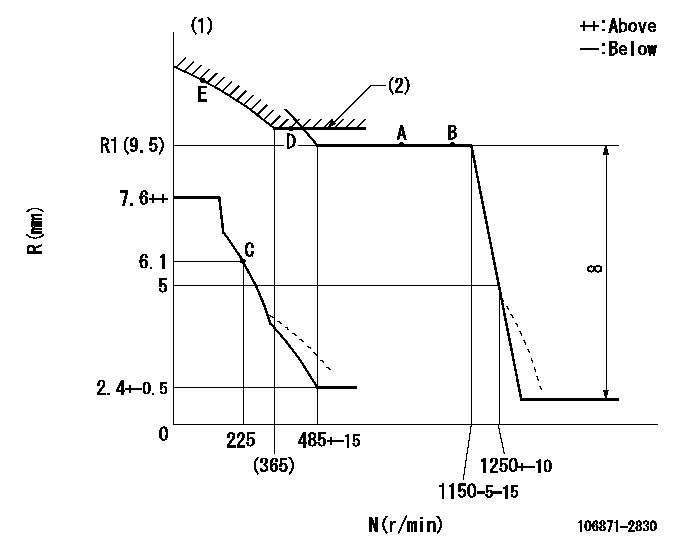
N:Pump speed
R:Rack position (mm)
(1)Damper spring setting: DL
(2)Excess fuel setting for starting: SXL
----------
DL=4.3-0.2mm SXL=10.2+-0.1mm
----------
----------
DL=4.3-0.2mm SXL=10.2+-0.1mm
----------
Speed control lever angle

F:Full speed
----------
----------
a=21deg+-5deg
----------
----------
a=21deg+-5deg
0000000901
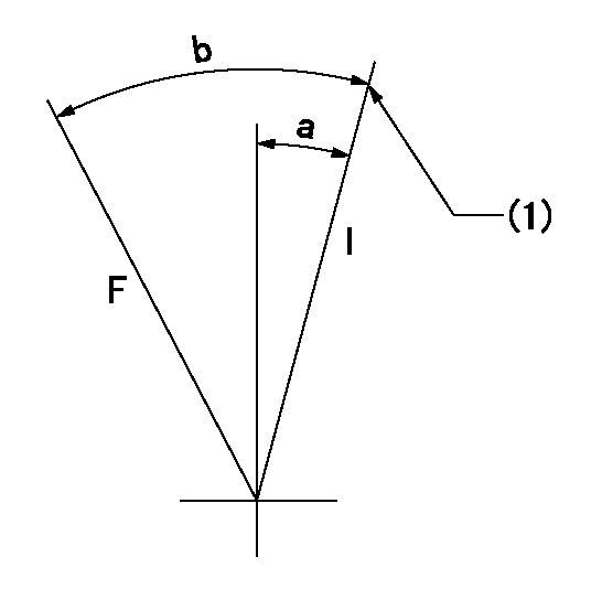
F:Full load
I:Idle
(1)Stopper bolt setting
----------
----------
a=10deg+-5deg b=26deg+-3deg
----------
----------
a=10deg+-5deg b=26deg+-3deg
Stop lever angle
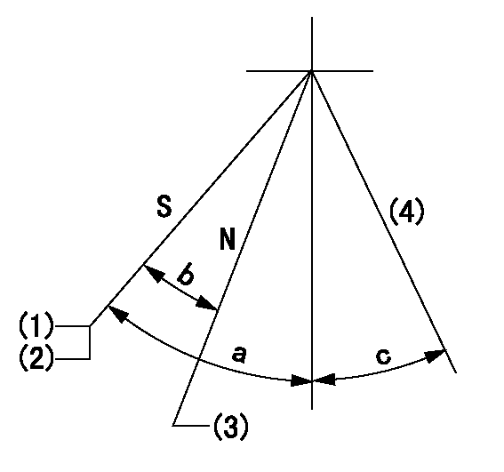
N:Engine manufacturer's normal use
S:Stop the pump.
(1)Rack position = aa
(2)Stopper bolt setting
(3)Rack position bb
(4)Free (at shipping)
----------
aa=4-0.5mm bb=11.7mm
----------
a=43deg+7deg-5deg b=21.5deg+-5deg c=(10.5deg)
----------
aa=4-0.5mm bb=11.7mm
----------
a=43deg+7deg-5deg b=21.5deg+-5deg c=(10.5deg)
0000001501 MICRO SWITCH
Adjustment of the micro-switch
Adjust the bolt to obtain the following lever position when the micro-switch is ON.
(1)Speed N1
(2)Rack position Ra
----------
N1=325+-5r/min Ra=5.6mm
----------
----------
N1=325+-5r/min Ra=5.6mm
----------
0000001601 ACS
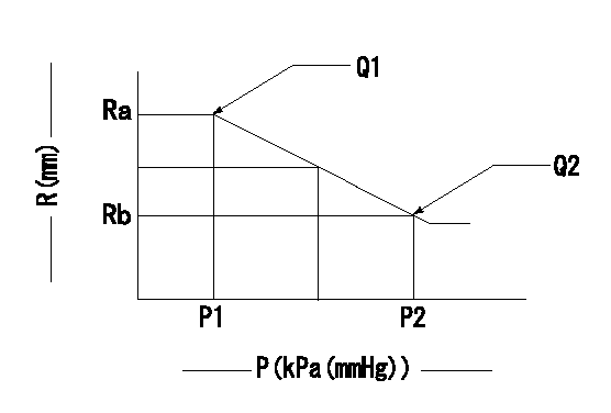
Aneroid compensator adjustment
(1)Adjust the clearance between the aneroid compensator's main body and the push rod to L1.
(2)Pump speed N1 at load lever's full position.
(3)Screw in the aneroid compensator body to obtain the performance shown in the graph above.
----------
L1=0.1~0.5mm N1=700r/min
----------
Ra=9.5mm Rb=9.1mm P1=(97.3)kPa((730)mmHg) P2=84.6+-0.7kPa(635+-5mmHg) Q1=118+-1cm3/1000st Q2=108.6+-3cm3/1000st
----------
L1=0.1~0.5mm N1=700r/min
----------
Ra=9.5mm Rb=9.1mm P1=(97.3)kPa((730)mmHg) P2=84.6+-0.7kPa(635+-5mmHg) Q1=118+-1cm3/1000st Q2=108.6+-3cm3/1000st
Timing setting

(1)Pump vertical direction
(2)Coupling's key groove position at No 1 cylinder's beginning of injection
(3)-
(4)-
----------
----------
a=(40deg)
----------
----------
a=(40deg)