
Rating:
Information injection-pump assembly
BOSCH
9 400 615 952
9400615952
ZEXEL
101671-9830
1016719830
NISSAN-DIESEL
1671795012
1671795012
Cross reference number
BOSCH
9 400 615 952
9400615952
ZEXEL
101671-9830
1016719830
NISSAN-DIESEL
1671795012
1671795012
Zexel num
Bosch num
Firm num
Name
9 400 615 952
1671795012 NISSAN-DIESEL
INJECTION-PUMP ASSEMBLY
ND605 * K 14BE PE6A PE
ND605 * K 14BE PE6A PE
Calibration Data:
Adjustment conditions
Test oil
1404 Test oil ISO4113 or {SAEJ967d}
1404 Test oil ISO4113 or {SAEJ967d}
Test oil temperature
degC
40
40
45
Nozzle and nozzle holder
105780-8140
Bosch type code
EF8511/9A
Nozzle
105780-0000
Bosch type code
DN12SD12T
Nozzle holder
105780-2080
Bosch type code
EF8511/9
Opening pressure
MPa
17.2
Opening pressure
kgf/cm2
175
Injection pipe
Outer diameter - inner diameter - length (mm) mm 6-2-600
Outer diameter - inner diameter - length (mm) mm 6-2-600
Tester oil delivery pressure
kPa
157
157
157
Tester oil delivery pressure
kgf/cm2
1.6
1.6
1.6
Direction of rotation (viewed from drive side)
Right R
Right R
Injection timing adjustment
Direction of rotation (viewed from drive side)
Right R
Right R
Injection order
1-4-2-6-
3-5
Pre-stroke
mm
2.5
2.45
2.55
Beginning of injection position
Drive side NO.1
Drive side NO.1
Difference between angles 1
Cal 1-4 deg. 60 59.5 60.5
Cal 1-4 deg. 60 59.5 60.5
Difference between angles 2
Cyl.1-2 deg. 120 119.5 120.5
Cyl.1-2 deg. 120 119.5 120.5
Difference between angles 3
Cal 1-6 deg. 180 179.5 180.5
Cal 1-6 deg. 180 179.5 180.5
Difference between angles 4
Cal 1-3 deg. 240 239.5 240.5
Cal 1-3 deg. 240 239.5 240.5
Difference between angles 5
Cal 1-5 deg. 300 299.5 300.5
Cal 1-5 deg. 300 299.5 300.5
Injection quantity adjustment
Adjusting point
A
Rack position
12.1
Pump speed
r/min
750
750
750
Average injection quantity
mm3/st.
65.7
64.7
66.7
Max. variation between cylinders
%
0
-2.5
2.5
Basic
*
Fixing the lever
*
Injection quantity adjustment_02
Adjusting point
B
Rack position
11.4
Pump speed
r/min
750
750
750
Average injection quantity
mm3/st.
57.3
55.8
58.8
Max. variation between cylinders
%
0
-4
4
Fixing the rack
*
Injection quantity adjustment_03
Adjusting point
C
Rack position
7.4+-0.5
Pump speed
r/min
300
300
300
Average injection quantity
mm3/st.
9
7.8
10.2
Max. variation between cylinders
%
0
-13
13
Fixing the rack
*
Remarks
Adjust only variation between cylinders; adjust governor according to governor specifications.
Adjust only variation between cylinders; adjust governor according to governor specifications.
Timer adjustment
Pump speed
r/min
300
Advance angle
deg.
0.5
Timer adjustment_02
Pump speed
r/min
600
Advance angle
deg.
1.3
0.8
1.8
Timer adjustment_03
Pump speed
r/min
900
Advance angle
deg.
2.9
2.4
3.4
Timer adjustment_04
Pump speed
r/min
-
Advance angle
deg.
6
6
6
Remarks
Measure the actual speed, stop
Measure the actual speed, stop
Test data Ex:
Governor adjustment
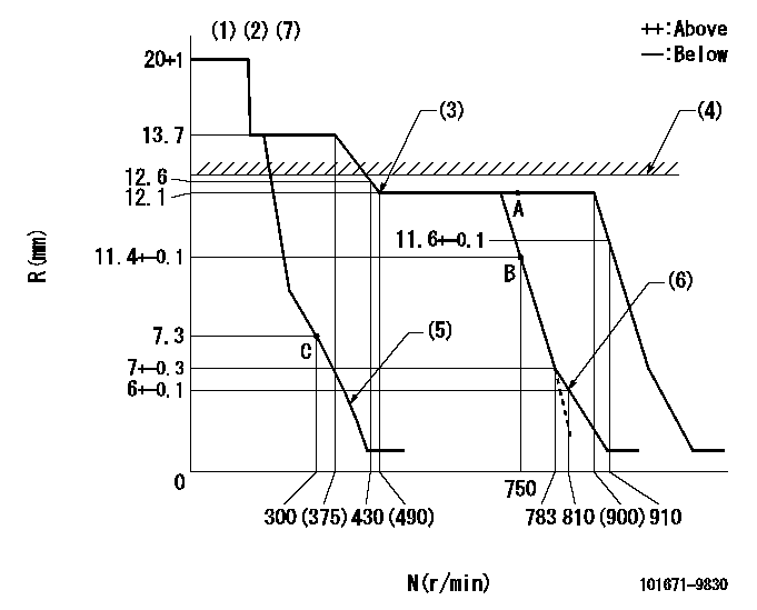
N:Pump speed
R:Rack position (mm)
(1)Target notch: K
(2)Tolerance for racks not indicated: +-0.05mm.
(3)Set the idle spring.
(4)RACK LIMIT: RAL
(5)Main spring setting
(6)Set idle sub-spring
(7)Solenoid operation confirmation
1. Set the speed control lever in the full position.
2. Operate the solenoid at speed N1.
3. Confirm that the rack position does not exceed the idle rack position - Ra.
4. Confirm in the same way using the manual lever.
----------
K=8 RAL=12.7+-0.1mm N1=100r/min Ra=1mm
----------
----------
K=8 RAL=12.7+-0.1mm N1=100r/min Ra=1mm
----------
Speed control lever angle
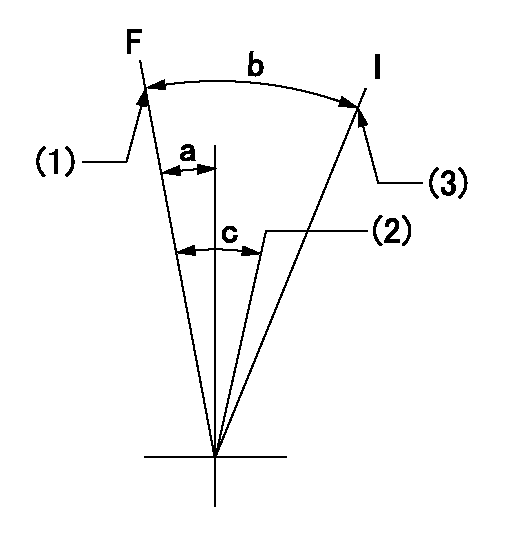
F:Full speed
I:Idle
(1)Speed set at aa (setting at supply)
(2)Set the pump speed at bb.
(3)Stopper bolt setting
----------
aa=900r/min bb=750r/min
----------
a=(1deg)+-5deg b=(23deg)+-5deg c=(6deg)+-5deg
----------
aa=900r/min bb=750r/min
----------
a=(1deg)+-5deg b=(23deg)+-5deg c=(6deg)+-5deg
Stop lever angle
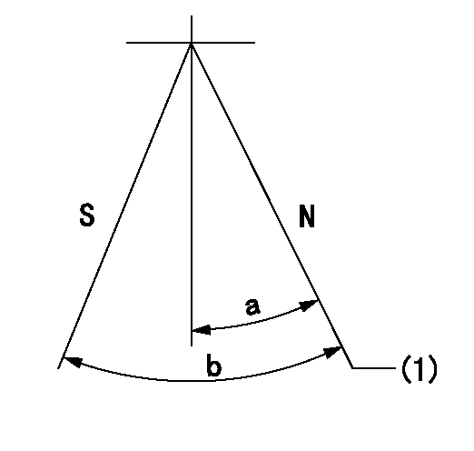
N:Pump normal
S:Stop the pump.
(1)Normal
----------
----------
a=(29deg) b=(47deg)
----------
----------
a=(29deg) b=(47deg)
0000001501 GOV FULL LOAD ADJUSTMENT
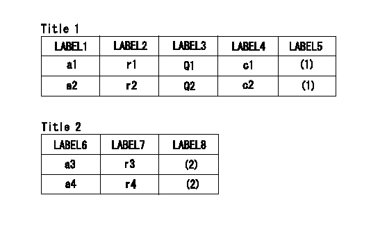
Title1:Full load stopper adjustment
Title2:Governor set speed
LABEL1:Distinguishing
LABEL2:Pump speed (r/min)
LABEL3:Ave. injection quantity (mm3/st)
LABEL4:Max. var. bet. cyl.
LABEL5:Remarks
LABEL6:Distinguishing
LABEL7:Governor set speed (r/min)
LABEL8:Remarks
(1)Adjustment conditions are the same as those for measuring injection quantity.
(2)-
----------
----------
a1=B a2=- r1=750r/min r2=- Q1=65.7+-1mm3/st Q2=- c1=+-2.5% c2=- a3=- a4=- r3=- r4=-
----------
----------
a1=B a2=- r1=750r/min r2=- Q1=65.7+-1mm3/st Q2=- c1=+-2.5% c2=- a3=- a4=- r3=- r4=-